| Max Feed: 15 GPH (56.8 LPH) |
| Max Pressure: 150 PSI (10.3 bar) |
C-1100 Variable Speed Pumps
C-1100V (digital display control)
- Manual or Automatic control
- Accepts 4-20mA, 0-10VDC, and pulse input signals
- Mechanical stroke length adjustment (cam type)
- 1 amp alarm output relay
- Digital touch-pad with LCD
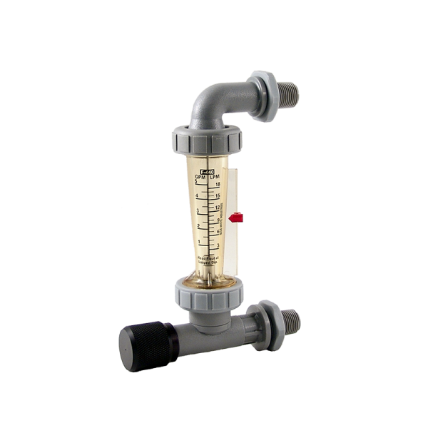
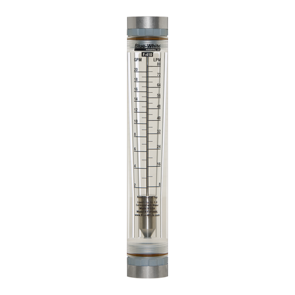
- Flow Verification Sensor (FVS) compatible.
| LITERATURE | DOWNLOAD |
| Tech. Data Sheet (PDF) (PN 85000-049) | Download |
| Instruction Manual (PDF) (PN 80000-387) | Download |
C-1100F (dial knob control)
- Manual output control
- EasyDial knob style – output percentage speed adjustment
- Mechanical stroke length adjustment (cam type)
- Nothing to program
- 5 – 100% output adjustment
- On-Off power switch
| LITERATURE | DOWNLOAD |
| Tech. Data Sheet (PDF) (PN 85000-050) | Download |
| Instruction Manual (PDF) (PN 80000-363) | Download |
C-1100 Fixed Speed Pumps
C-1100E (digital display control)
- Digital interval timer for near infinite turndown ratio
- Repeating interval and injection time cycles programmable in seconds, minutes, hours, and days
- Accepts 4-20mA, 0-10VDC, and pulse input signals
- Flow Verification Sensor (FVS) compatible.
| LITERATURE | DOWNLOAD |
| Tech. Data Sheet (PDF) (PN 85000-053) | Download |
| Instruction Manual (PDF) (PN 80000-364) | Download |
C-1100C (time interval control – 5 second cycle timer)
- Precise output control to 20:1 turndown by means of dial knob
- 5 second repeating timer cycle
- 0.25 – 5 second adjustable feed (injection) time per cycle
| LITERATURE | DOWNLOAD |
| Tech. Data Sheet (PDF) (PN 85000-051) | Download |
| Instruction Manual (PDF) (PN 80000-363) | Download |
C-1100A (time interval control – 60 second cycle timer)
- Precise output control to 20:1 turndown by means of dial knob
- 60 second repeating time cycle
- 3 – 60 second adjustable feed (injection) time per cycle
| LITERATURE | DOWNLOAD |
| Tech. Data Sheet (PDF) (PN 85000-052) | Download |
| Instruction Manual (PDF) (PN 80000-363) | Download |
C-1100X (continuous feed time / always on)
- Fixed speed – no output control
- No adjustment mechanism
- Low cost OEM model
| LITERATURE | DOWNLOAD |
| Tech. Data Sheet (PDF) (PN 85000-054) | Download |
| Instruction Manual (PDF) (PN 80000-363) | Download |
Variable Speed Models (continuous pulse free output)
Continuous pumping, even while adjusting the percentage of output. See image below.
Graphical representation of the variable speed diaphragm pump injection characteristics.
Note: Your chemical or solution is mixed in the fluid. This image is only illustrating the feed characteristics.

Fixed Speed Models (intermittent cycle time output)
You control the pumps feed by using timers (built-in or external). See image below.Usually fixed speed outputs can be adjusted by:
- Selecting the pump head diaphragm size.
- Manual stroke length adjustment (cam style).
- Choosing the desired RPM (revolutions per minute).
Graphical representation of the fixed speed diaphragm pump injection characteristics.
Note: Your chemical or solution is mixed in the fluid. This image is only illustrating the feed characteristics.


| LITERATURE | DOWNLOAD |
|---|---|
| Exploded View(PDF) |
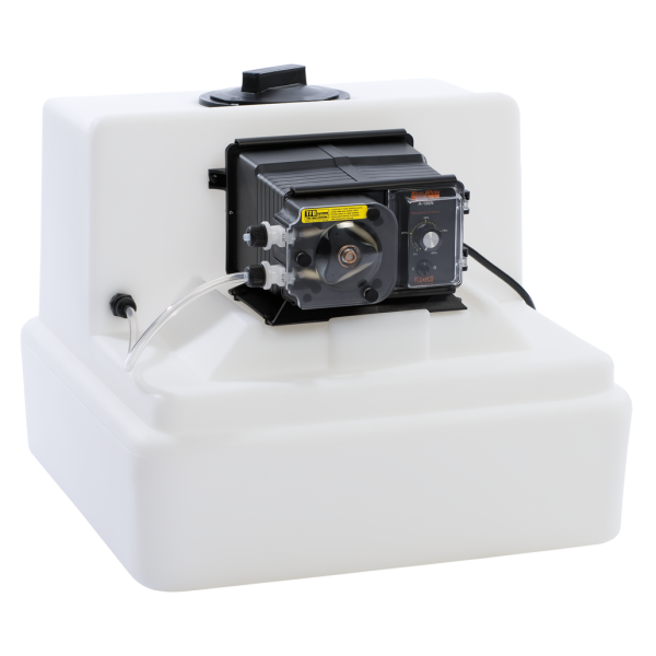
Installation Example of C-1100 CHEM-FEED® Diaphragm Metering Pump

Mounting Options:
| WALL MOUNT | SHELF MOUNT |
|---|---|
 |
 |
Mounting Location:
- Choose an area located near the chemical supply tank, chemical injection point and electrical supply. Although the pump is designed to withstand outdoor conditions, a cool, dry, well ventilated location is recommended. Install the pump where it can be easily serviced.
- Mount the pump to a secure surface or wall using the enclosed hardware. Wall mount to a solid surface only. Mounting to drywall with anchors is not recommended.
- Do not mount the pump directly over your chemical container. Chemical fumes may damage the unit. Mount the pump off to the side or at a lower level than the chemical container opening.
- Mounting the pump lower than the chemical container will gravity feed the chemical into the pump. This “flooded suction” installation can reduce the time required to prime the pump. Install a shut-off valve, pinch clamp or other means to halt the gravity feed to the pump during servicing.
- Your solution tank should be sturdy. Keep the tank covered to reduce fumes.
- Be sure your installation does not constitute a cross connection with the drinking water supply. Check your local plumbing codes.